gavs
Передовик
Сообщения: 1292
|
Dear imran khan,
you had described the one of typical LCD-panels failures – horizontal block defect (by good known Samsung classification). This defect occurs when one or some of gate drivers are defective or if contacts between gate driver IC and TCO wires on glass are lost. If gate drivers had placed in TCP-cases, usually mounted at the right side of the screen, you have a good chance to restore the LCD-panel, if gate drivers had installed by chip on glass technology – LCD-panel can be restored only at factory. Personally I consider that complicated repair of 17” TN LCD-panel is BER – your labor time costs much in compare with restored unit cost. Sometime I restore 19” IPS or higher grade panels. You can read at the next topic for some detail: http://monitor.espec.ws/section33/topic210166.html |
|
gavs
Передовик
Сообщения: 1292
|
imran khan,
Try to use translate.google.com or translate.ru online services. Using Google translation service I tried to read, for example, Chinese web-pages, which contains a lot of technical information, and I had understood the basic meaning of mentioned pages.
Due to your defect.
The slow image refresh can be explained by low TFT gates open voltage value. If slow refresh presents at the whole screen, trouble is in DC-DC converter, placed on T-CON PWB, most frequently. If the slow image refresh presents only on partial horizontal areas with sharp edges, it can be explained only by problems with gate drivers.
If you remove bezel, you can find some “small flags”, glued to the glass of LC-unit at right side of LCD-panel. They are gate driver IC’s in TCP-cases. You can see the typical gate driver IC on the picture:
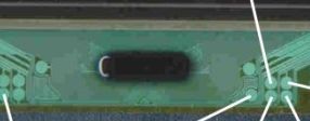
You see that gate driver IC contains some control pads. Unfortunately, any technical documentation for gate drivers is absent and you need to define nets, connected to those pads. There are three kinds of signals, connected them:
1. Start pulse – short pulse with vertical refresh frequency, clock pulse – nearby square wave with horizontal refresh frequency, output enable signal – like as clock signal, but with phase shift and output drive pulse for the next IC driving. All gate divers connects as daisy chain and summary they corresponds the huge shift register. Output pulse of the first driver is start pulse for the second driver etc. Clock and OE – common drive signals for all drivers. All this signals are nearby 3V p-p amplitude (standard logic levels).
2. Power. For correct working of the gate driver it needs in the list of voltages: Vg on; Vg off, Vcc, Vcom, GND. On some panels this acronyms might be difference.
3. Outputs, connected in parallel with first and last outputs only (it’s impossible to connect all, for example, 384 outputs to control pads, all outputs connects to ITO conductors on glass via ACF). This control pads can be used for drivers outputs checking. This signals might have nearby 30V p-p amplitude.
At first you should define control pads assignment. It can do only you while using multimeter for check connections to of control pads on gate drivers and on T-CON PCB and while checking waveforms using oscilloscope. If you find abnormal value of any supply voltage on driver, you can connect the control pad to the similar control pad on next driver or to the control pad on T-CON PCB, connected to the same circuit using thin hookup wire. While using multimeter you should take into account that connections thru ACF (anisotropic conductive film) and ITO wires can have high resistance and multimeter can not “bee” in ringup mode. |
|
